A Matter of Millimeters
On the 4th of November 2010, a Qantas Airbus A380 was rocked by a catastrophic engine failure minutes after takeoff from Singapore, hurling fragments of a turbine disk through its wings and fuselage i
On the 4th of November 2010, a Qantas Airbus A380 was rocked by a catastrophic engine failure minutes after takeoff from Singapore, hurling fragments of a turbine disk through its wings and fuselage in multiple locations. The explosion damaged almost every major system on the airplane, from the flight controls and fuel tanks to hydraulics and pneumatics. Faced with a barrage of diverse failure warnings and an airplane of uncertain integrity, the flight crew worked together to make a series of critical decisions that would get their enormous airplane back on the ground. And in the end, despite one curveball after another — including landing gear problems, loss of braking power, and an engine that refused to shut down — they not only landed the plane, but did so without putting a scratch on any of the 469 passengers and crew.
The cause of the incident would ultimately be traced deep inside the number two engine to a single oil pipe that had been manufactured with a wall that was slightly too thin. How this seemingly tiny defect came about, and how it nearly brought down the world’s largest passenger plane, represent a story equally as fascinating as that of the flight itself, tracing back years to encompass questionable drawing board decisions, hidden flaws in the machining logic, and faulty assumptions about engine behavior. Time and time again, the problem slipped through the gaps in the system, tumbling down the long slope toward disaster — only to be stopped at the last moment, not only by the pilots themselves, but by a number of explicit protections built into the design of the A380, each of which played a crucial role in containing the fallout from a failure that exceeded the manufacturer’s worst expectations. The story of Qantas flight 32, as told herein, is therefore not only the tale of a dramatic emergency, but a testament to the safety of aviation today — a story that should make every reader feel a little less fearful of flight.
◊◊◊
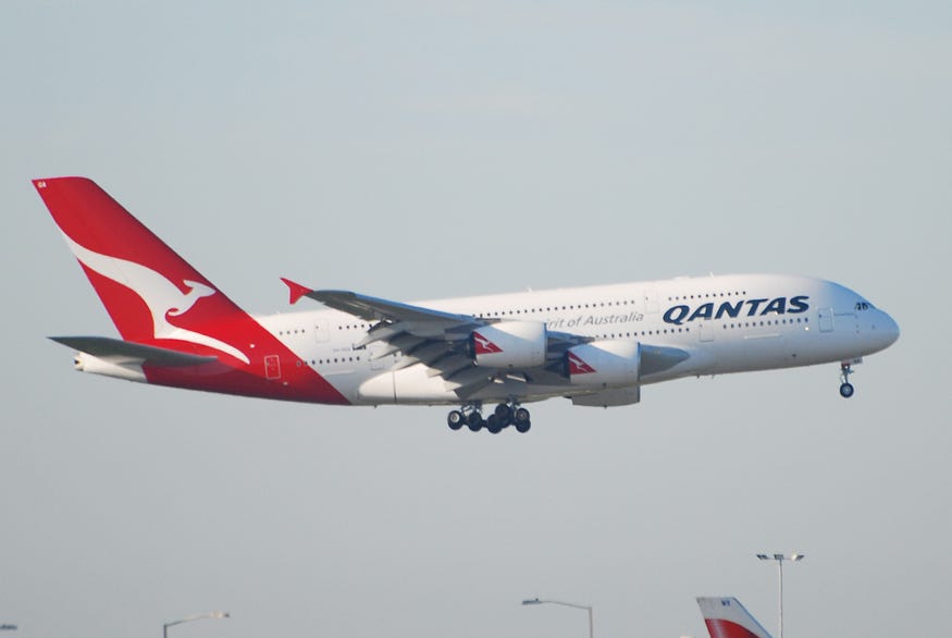
A brand new Airbus A380 takes to the skies. (Pascal Le Segretain)
Introduced to service in 2007, the double decker, four-engine A380 is by far the largest passenger aircraft in the world, exceeding the vaunted Boeing 747 in almost every measurement. Awesome to behold and pleasant to fly, there’s not much to dislike about the A380 — unless you’re an airline, in which case most major carriers dismissed the behemoth as too large for their operating models. Indeed, analysts’ assessment today is that the A380 was built for a market that had shrunk considerably by the time it actually entered service, and as a result, production ended in 2021 with only 254 built, some of which have already been scrapped. For an extraordinarily expensive aircraft equipped with some of the most advanced technology of any airliner, the collective result of immense effort and imagination, such a fate is unfortunate, but the reasons behind it, and the future of the type, are topics for a different article.
Despite the above, some airlines did find the A380 suitable for their operations, including Qantas, the flag carrier of Australia. Qantas ordered 12 A380s to be delivered in 2008, of which ten are still flying today. It was the very first of these, registered as VH-OQA and nicknamed Nancy-Bird Walton after the pioneering Australian aviator, that would come to be involved in the events of the 4th of November 2010.
VH-OQA, the aircraft involved in the accident. (Andrei Dimofte)
On that date, VH-OQA arrived in Singapore for a scheduled stopover on a marathon London-to-Sydney trip, where it took on fuel, passengers, and a new flight crew for the last leg to Australia. The plane was essentially full, with 440 of 450 passenger seats filled, plus a massive complement of 29 crewmembers, including no less than five pilots. Although the A380 is normally flown by only two pilots, Qantas had also rostered a second officer as a relief crewmember; a check airman was conducting a line check on the captain; and another check airman was training the first check airman, so the cockpit was certainly crowded.
In command, and under examination, was 53-year-old Captain Richard Champion de Crespigny, a veteran airman with over 15,000 hours of experience and 32 years in aviation. The other crewmembers consisted of First Officer Matt Hicks, Second Officer Mark Johnson, Check Captain Harry Wubben, and Senior Check Captain David Evans. The five crewmembers had a combined 140 years in aviation and 71,000 hours of flying experience, an incredible total that is rarely equaled.
At 9:56 a.m. local time, with Captain de Crespigny at the controls, Qantas flight 32 departed Singapore and proceeded southeast across the strait toward Indonesia, passing over the densely populated island of Batam. All parameters still appeared normal as the A380 climbed through 7,000 feet, four minutes after takeoff. There was no indication that a catastrophic failure was in fact just seconds away.
◊◊◊
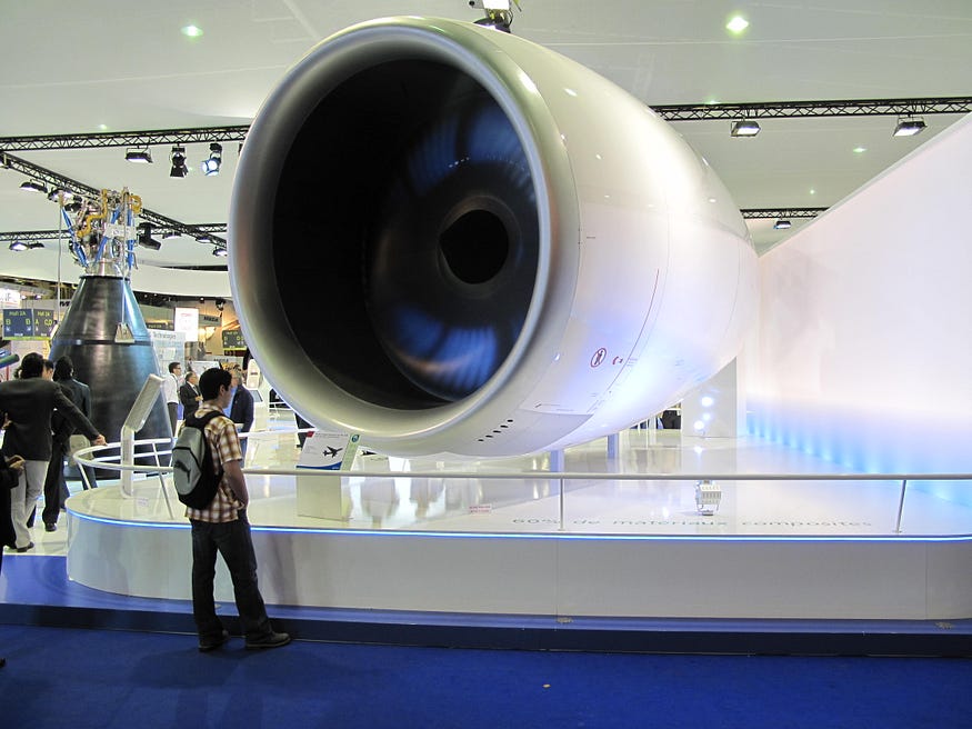
A Rolls-Royce Trent 900 engine with a man for scale. (Wikimedia user Tangopaso)
The Airbus A380 is powered by four massive Rolls-Royce RB211 Trent 900-series high-bypass turbofan engines, each producing up to 84,000 lbf of thrust. Designed specifically for the A380, the Trent 900 was produced at several locations in the United Kingdom and was sold in competition with the American-built GP7200 jointly developed by Pratt & Whitney and General Electric.
Understanding what happened aboard Qantas flight 32 requires that I subject you to a description of the structure of certain very specific parts of the engine.
Like all high-bypass jet engines, the Trent 900 consists of four main sections: the fan, the compressors, the combustion chamber, and the turbines. During normal operation, air is forced backward and pressurized by a series of increasingly powerful compressors before being fed into the combustion chamber, where it is mixed with fuel and ignited. The combustion creates mechanical energy that spins a series of turbines, which in turn power the compressors, as well as the fan at the front of the engine, which accelerates large quantities of so-called bypass air around the outside of the engine core to generate most of the thrust output.
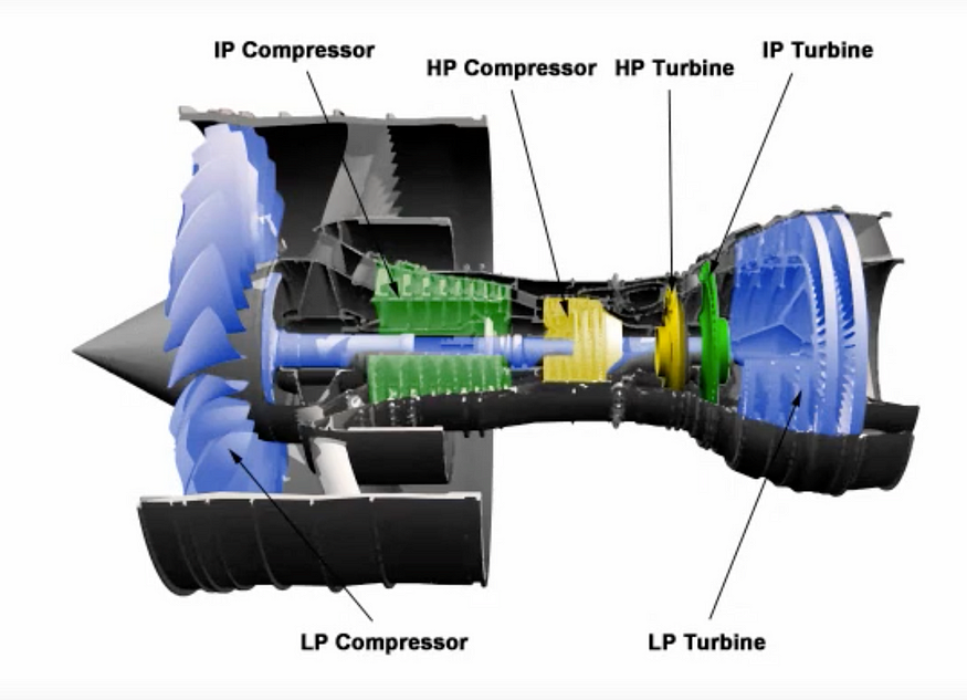
Locations of turbines and compressors on the Trent 900. (FAA)
Most turbofan engines examined in my articles have a high pressure compressor and a low pressure compressor, which correspond to high- and low-pressure turbines. These turbines are connected to their respective compressor sections by concentric drive shafts. However, the Trent 900 differs from this layout slightly, because it also has an intermediate pressure compressor with a corresponding intermediate pressure turbine, in between the high and low pressure sections. It also differs in that the fan itself doubles as the low pressure compressor. (From now on, for brevity’s sake, the abbreviations LP, IP, and HP will be used for low pressure, intermediate pressure, and high pressure, respectively.)
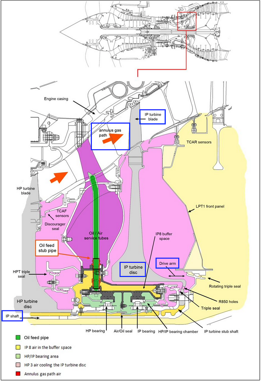
In this cutaway diagram of the IP turbine area, I’ve drawn blue boxes around the components mentioned in the following paragraph. (ATSB)
On the Trent 900, the HP and IP turbine sections at the rear of the engine each consist of a single-stage turbine disk. Blades around the circumference of each disk capture mechanical energy from hot combustion gases flowing through what is known as the “annulus gas path.” These gases spin the disk, which is attached by a drive arm to its associated drive shaft. The shaft then transfers the turbine’s rotational energy forward to the corresponding compressor at the front of the engine.
This clip from an FAA video helps visualize the cutaway of the HP/IP bearing assembly. Note the location of the bearing chamber, which is depicted full of oil, and the pipe leading into it. Watch the full video here: https://www.youtube.com/watch?v=sYxVin_FFxQ
In order to support the turbine disks and shafts while still allowing them to rotate freely, the engine features a complex system of bearings. The HP and IP turbine sections have a common bearing assembly, called the HP/IP bearing hub, which encircles the drive shafts and holds them in place while allowing free rotation of the shafts within.
To prevent wear on the bearings, the space inside the bearing hub, called the bearing chamber, is constantly filled with pressurized oil that keeps everything gliding smoothly. This oil is supplied primarily by an oil feed pipe that runs from the main engine oil supply, past the annulus gas path, and down into the HP/IP bearing hub, where it injects oil through a filter and into the bearing chamber.
The structure of the bearing hub consists of an inner and outer hub section, such that an empty buffer space exists between the bearing chamber and the rest of the engine. The oil feed pipe runs through both sections in order to reach the bearing chamber. The last segment of this pipe, a few centimeters in length, is welded in place during manufacture of the bearing hub, and the main portion of the pipe is fitted to it later. This fixed final segment that passes through the buffer space between the inner and outer sections of the HP/IP bearing hub is called the “stub pipe.”
For reasons that will be examined in detail later, this tiny oil feed stub pipe triggered an escalating sequence of events within the space of mere seconds as Qantas flight 32 climbed away from Singapore.
Within the №2 engine, located in the inboard position on the left wing, a crack in the oil feed stub pipe caused it to begin leaking oil less than four minutes after takeoff. The leak was small, but the oil within the pipe was highly pressurized, resulting in an atomized spray into the buffer space between the inner and outer sections of the HP/IP bearing hub. The temperature inside this buffer space was likely between 365 and 375˚C, well above the 280-degree auto-ignition temperature of the engine oil, so the spray immediately ignited.
An FAA animation of the failure sequence leading up to the explosion aboard Qantas 32, annotated by me. This should be really helpful for visualizing the following paragraph. (FAA)
At the forward end of the bearing hub, a triple seal is attached to the hub structure to isolate the buffer space, which has a low internal pressure, from the area behind the high pressure turbine disk, where pressure is higher. But as the fire in the buffer space expanded, it impinged upon this seal, causing it to fail. With the low-pressure area no longer sealed off, highly pressurized air from the annulus gas path was drawn toward it, bursting down past the high pressure turbine disk and into the buffer space. This rush of air coming in through the forward end of the buffer space blasted the fire aft, propelling it like a blowtorch against the corresponding seal at the other end, which also failed. The burning oil “blowtorch” was then able to make direct contact with the drive arm connecting the IP turbine disk to its drive shaft, located directly behind the HP/IP bearing hub. Already under considerable stress as a result of normal engine operation, the drive arm failed under the withering heat within a matter of seconds.
This entire sequence, from the initiation of the oil leak to the failure of the drive arm, lasted considerably less than one minute.
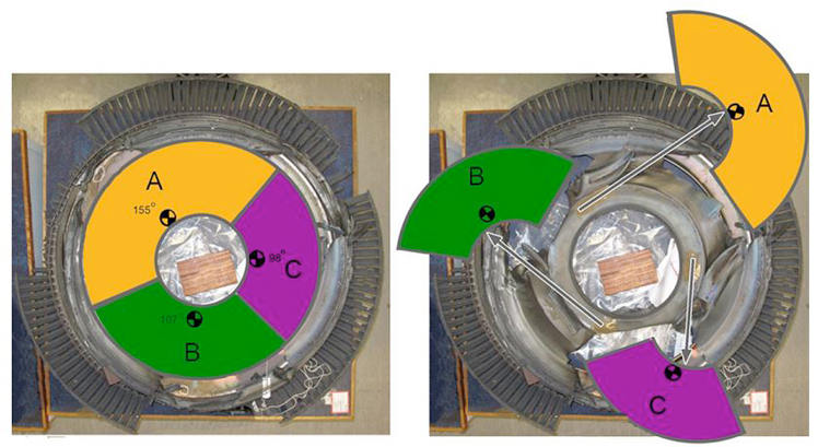
The turbine disk disintegrates. (ATSB)
Now, with the drive arm broken, the IP turbine disk was not directly connected to anything, which is (to use the technical jargon) a really big problem. A turbine disk is subjected to considerable mechanical energy from the annulus gas path, and that doesn’t go away when the drive arm breaks, but what does go away is any ability to transfer that energy somewhere other than the turbine disk itself. During normal operations, this energy is used to turn the intermediate compressors, which requires considerable force. But this load path only exists when the turbine disk is connected to the drive shaft, so when the drive arm broke, the only way for the disk to absorb all that energy was to spin faster… and faster… and faster…
Within the space of four seconds, the energy from the annular gas flow accelerated the IP turbine past its critical speed, until centrifugal forces exceeded the ultimate strength of the nickel alloy disk. The red-hot, wildly spinning disk instantly fractured into several sections, which rocketed outward in multiple directions at incomprehensible speed.
The disk fragments neatly ripped out everything within the disk’s plane of rotation. (ATSB)
Engine designers do their best to make sure that the engine structure can contain flying debris like individual fan and turbine blades, but the amount of energy contained within those types of projectiles is a fraction of that within a piece of a burst disk. For engineering purposes, disk fragments are assumed to have infinite energy at the moment of release; they will cut through any reasonable material and cannot be contained.
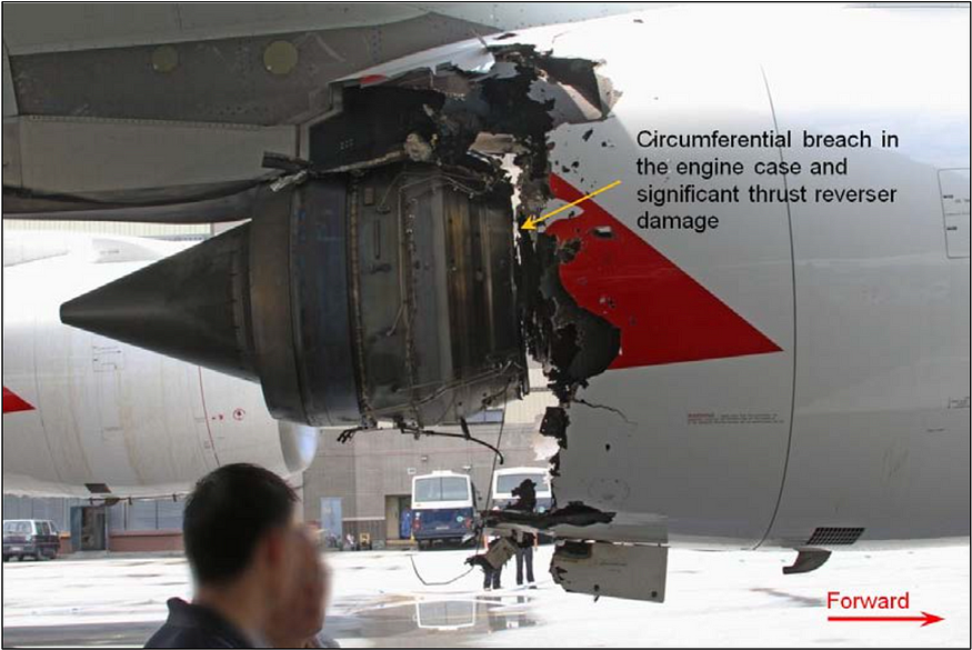
When the IP turbine disk on Qantas flight 32 suddenly burst, nothing could stop the resulting fragments, which cut through the engine case and cowling like butter, cleaving a neat circumferential fissure all the way around the engine within the plane where the disk used to be. Within a fraction of a second, one of these disk fragments exited the engine downward and to the left, propelled toward the distant ground, but several more traveled in the opposite direction. One fragment shot to the right, entered the belly area below the cargo hold, plowed through several structural stringers and wire bundles, then exited out the other side, never to be seen again. Two more fragments rocketed upward, carving paths of destruction through the interior of the left wing before emerging from its upper surface, at which point they too disappeared into space. Numerous smaller pieces, such as dislodged turbine blades and fragments of engine structure, also peppered various parts of the aircraft, including the wings and fuselage.
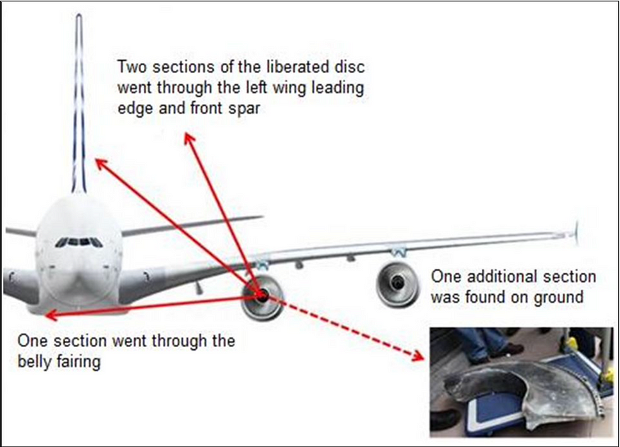
The trajectories of the various fragments. (ATSB)
On board the plane, the pilots and passengers heard two distinct bangs in very short succession, which were followed in the cockpit by a sudden, overwhelming cascade of warnings. The plane yawed slightly to the left and the autothrust system disconnected. Recognizing that a serious malfunction had occurred, Captain de Crespigny pressed the altitude hold button on the autopilot to level the plane, and then everyone’s attention turned to the ECAM.
The Electronic Centralized Aircraft Monitoring system, or ECAM, presents the crew with warnings, cautions, and advisories related to the degradation or failure of a huge range of aircraft systems, along with the associated abnormal or emergency procedures. A feature of most modern airliners, ECAM displays have transformed the way pilots deal with in-flight emergencies, helping ensure swift and correct action in response to almost any conceivable mechanical failure. Today, this system would be put to the test.
The first message to appear on the ECAM screen was an ENG 2 TURBINE OVERHEAT warning, which was followed within the next 20 seconds by another 34 messages of varying alert levels. The highest priority messages, displayed at the top of the list, all indicated a major problem with the №2 engine, but strangely enough, not its outright failure, because the engine — minus the IP turbine disk and everything in line with it — was in fact still turning. Following the indicated ECAM actions, Captain de Crespigny reduced power to the damaged engine, but instead of correcting the problem, an “ENG 2 FIRE” warning flashed on the screen for one or two seconds, then disappeared.
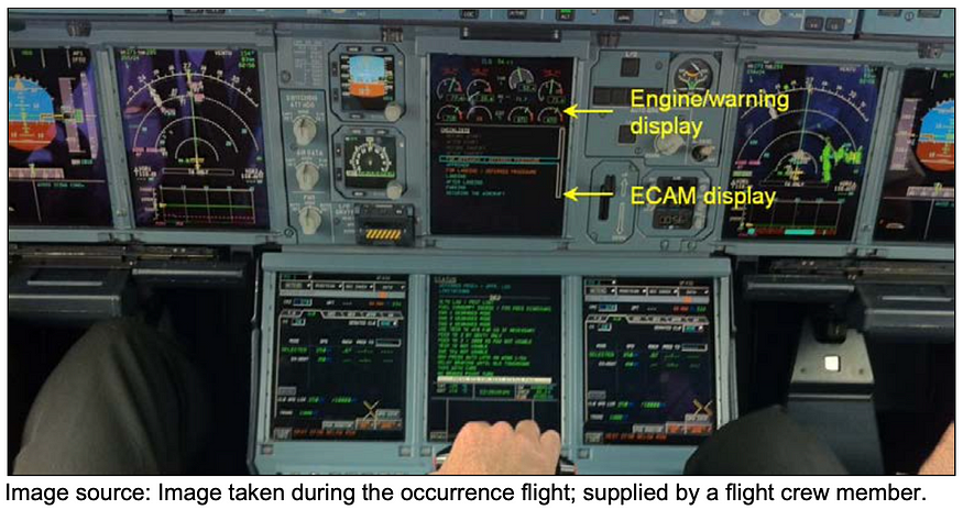
A flight crewmember took this photo of the instrument panel during the flight, showing several messages, including a red “warning” level message, on the ECAM display. (ATSB)
As First Officer Hicks made a pan-pan call to air traffic control, one level short of “mayday,” the crew decided that the engine was likely severely damaged and elected to shut it down. As they moved to reduce power, an ENG 2 FAIL message finally appeared on the ECAM. The pilots also attempted to actuate both of the engine’s two built-in fire extinguishers, but only one of them actually fired, and neither of the confirmation lights illuminated. However, as they scrolled through the seemingly unending list of ECAM alerts, only one or two of which could be displayed at one time, it became clear that the engine and its fire extinguishers were hardly the only systems having issues.
When the fragments of the IP turbine disk passed through the wing and belly of the A380, they caused considerable secondary damage along the way, not only to the №2 engine but also to the left wing fuel tank, which sprang a leak; the leading edge wing slat extension mechanism, which took a direct hit; and the aircraft’s electrical system. Additionally, two wire looms in the leading edge of the wing and in the belly area were completely severed, collectively affecting about 650 wires that carried critical information to and from almost every conceivable aircraft system. A brief and hardly exhaustive summary of the damage to the aircraft included impact damage to the left wing upper and lower skin, front spar, internal ribs, and wing-to-fuselage joint; loss of control over the green (left) hydraulic pumps; degradation of the yellow (right) hydraulic system; loss of AC electrical power from engines 1 and 2; loss of one of four AC power distribution systems; loss of functionality of all leading edge slats; partial loss of functionality of the spoilers and ailerons; degradation of control over all remaining engines, resulting in loss of the autothrust system; loss of functionality of the left wing landing gear brakes and anti-skid on the right wing gear brakes; severe disruption of the pneumatic system; loss of both the №1 and №2 low fuel pressure shutoff valves; degradation of the fuel quantity indicating system; reduction in fuel transfer capability; loss of the fuel jettison system; loss of fire protection capability on engines 1 and 2; and much more besides.
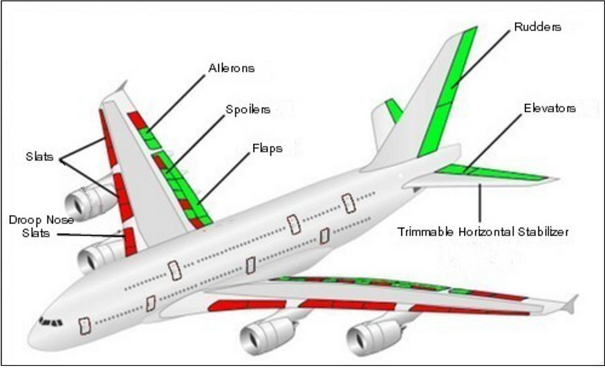
A map of operational flight controls surfaces [green] and inoperative surfaces [red]. (ATSB)
One of the most serious malfunctions was the loss of the green hydraulic system. Although the system itself was not breached, the severed wires stopped all the green hydraulic pumps, resulting in a loss of pressure that rendered inoperative all systems reliant upon it. Unlike some other wide body aircraft, the A380 has only two hydraulic systems — green and yellow — which mainly supply the left and right sides of the aircraft, respectively. Instead of more redundant hydraulic systems, the A380 has independent backup hydraulic actuators on each individual flight control surface, ensuring that even a total loss of both hydraulic systems will result in minimal flight control difficulties. Nevertheless, direct damage had degraded the plane’s roll control, eliminating the left middle aileron (the A380 has three on each wing) and left wing spoilers 4 and 6. The loss of green hydraulic pressure also caused the failure of the outboard ailerons on both wings, spoilers 2 and 8 on each wing, and spoiler 4 on the right wing. However, the built-in redundancy in the A380 was so great that the remaining spoiler and aileron panels were sufficient to maneuver the airplane despite what amounted to a 65% loss of roll control capability.
No comments yet. Login to start a new discussion Start a new discussion